
In this post I will describe the process to control my house heating system from the Internet using a Raspberry PI zero and a relay board, that can be programmed, controlled and report its status across the internet.
Since I moved in with my girlfriend I'm coming just from time to time to my old house in order to water the plants, clean a little bit or whatever. The other day I forgot to switch off the thermostat when I left the place and the heating system kept on for the next days with the consequent waste of energy and money. What I pity! As usual, I needed to find a technological solution to my bad head.
The first step was to unscrew the thermostat from the wall and disassemble it, this particular thermostat is pretty dumb, and it's just a wheel that opens or closes the boiler control circuit, if the circuit is opened the boiler stands still, if the circuit is closed then the boiler starts heating the house, I could even control the boiler just by touching and separating the cables (in fact I ended up controlling it like that for a couple of weeks).

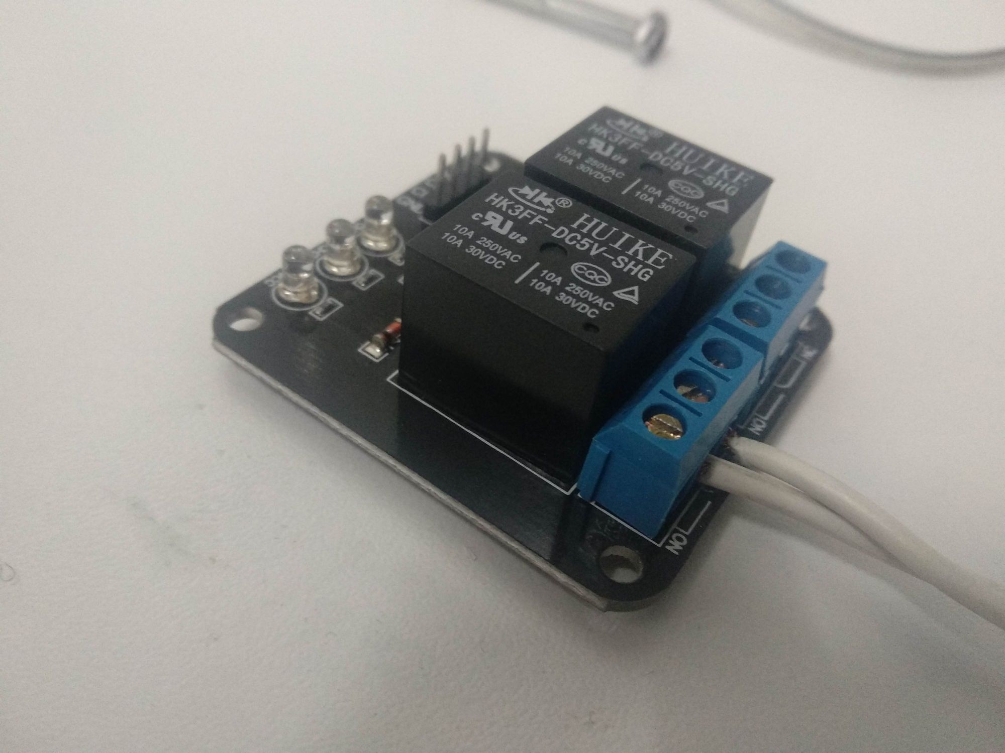
The next step was measuring the circuit voltage and intensity using a multimeter. The voltage marks 22.8 Volts and the current marks 20.5 mA so it is OK for the 5V relay I had lying around, you can see the relay allowed values written on top of it on the image below. I did a first test just connecting the two cables to the relay in the NC position, NC stands for normally closed, so in the absence of signal it should turn on the heater. This connection is doing by placing the negative current cable in the middle, and the positive where NC is written. The heater turned on as expected.
The next step then was to switch the cables position to the NO position, that stands for normally opened because I want the heater off by default, and it will be turned on when receiving an electrical signal from the Raspberry Pi. This is the GPIO schema:

The relay has 4 pins labeled as VCC, ground, Signal1 and Signal2, so the connection is very simple:
- GPIO 02 goes to the relay VCC.
- GPIO 06 goes to the relay ground.
- GPIO 04 goes to Signal1, this will send the "turn on" signal.
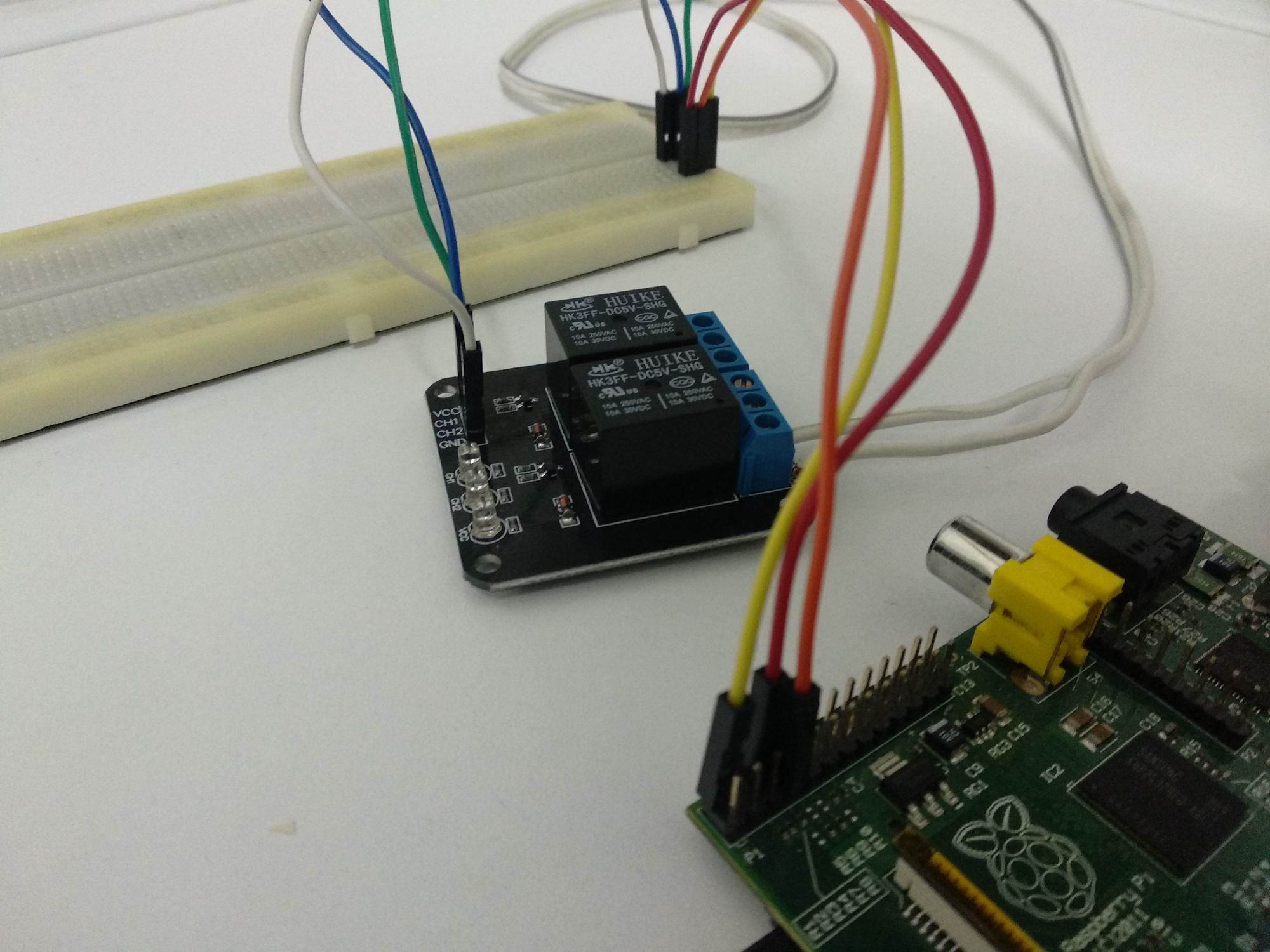
In this case I won't be using Signal2, it exists because this relay has actually two of them and could be used for driving another thing. Here is a picture of the resulting connection (breadboard in between not necessary).
The next step is to prepare your Raspberry Pi. I used an old Raspberry Pi 2 I bought some years ago I was not using. There are lots of tutorials on how to setup a headless Raspberry Pi with Raspbian in detail so I won't go in detail on this.
The last thing needed was to write a python script for making the Pi interact with the relay. I tested it with this little python script that will turn on the heater on and off every 15 seconds.
#!/usr/bin/python3
import RPi.GPIO as GPIO
from time import sleep
GPIO.setmode(GPIO.BCM)
GPIO.setwarnings(False)
GPIO.setup(4, GPIO.OUT)
while true:
  sleep(15)
  GPIO.output(4, GPIO.HIGH)
  sleep(15)
  GPIO.output(4, GPIO.LOW)
The script is very easy to understand for anyone who can read Python, also there is a nice documentation on the Python GPIO library documentation. Then I programmed the Pi to run the script when booting, then connected it and went to the heater to watch it turning on and off every 15 seconds making a clacking sound.
And that's all for now, the Pi has now the ability to turn on and off the heater thus the way of doing it is not very convenient because it is not on demand, but for this article is enough, in the next article I will connect the Pi to the network and turn the heater on from the distance.